Getting site lighting calculations right on the job site saves time, money, and prevents costly rework. Most contractors and property owners either guess at light levels or rely on overly complex methods that slow down projects.
We at OpenLumen built this guide to give you field-ready techniques that actually work. You’ll learn practical methods to calculate illuminance accurately, avoid common design mistakes, and know when to use manual calculations versus software tools.
Understanding Illuminance and Lighting Metrics
The Three Metrics That Control Your Site Calculations
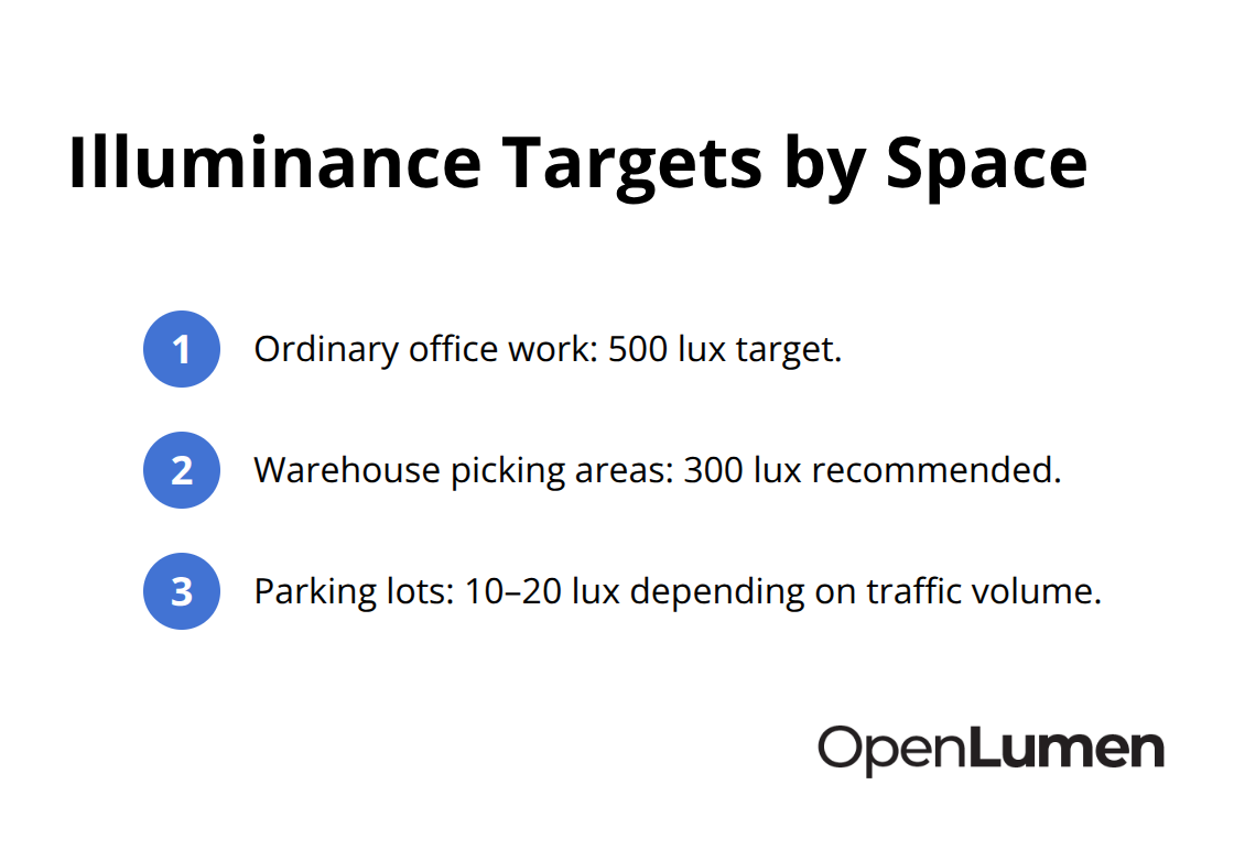
Illuminance, luminous intensity, and luminous flux form the foundation of every lighting calculation you’ll do on site. Illuminance, measured in lux, tells you how much light actually lands on a surface-this is what you care about most because it directly determines whether a space meets safety codes and task requirements. The IES Handbook and EN12464-1 standards define exact illuminance targets for different spaces: ordinary office work requires 500 lux, warehouse picking areas need 300 lux, and parking lots typically demand 10–20 lux depending on traffic volume.
Luminous intensity, measured in candela, describes how strong the light beam is in a specific direction-you’ll find this in the luminaire’s candlepower distribution curves, which show whether the fixture spreads light evenly or concentrates it in a tight cone. Luminous flux, measured in lumens, represents the total light output from a fixture; a typical 100-watt LED might produce 15,000 lumens, while a high-bay fixture could reach 50,000 lumens or more. Most contractors overlook the relationship between these three: flux is what you buy, intensity is what the fixture produces directionally, and illuminance is what actually shows up on your work surface.
When you read a luminaire datasheet, the manufacturer provides initial lumens, beam angle, and sometimes the candlepower distribution curve-but they rarely tell you the illuminance at 3 meters or 10 meters, so you have to calculate it yourself using the inverse square law.
How Surface Reflectance Affects Your Results
Surface reflectance values matter far more than most people realize because they directly affect how much light bounces back into your calculation. The IES Handbook recommends using 70–80% reflectance for ceiling materials, 50–70% for walls, and 10–30% for floors as starting points, but real job sites often differ significantly: a warehouse with painted concrete might have 40% ceiling reflectance instead of 80%, which reduces your effective illuminance by roughly 50%.
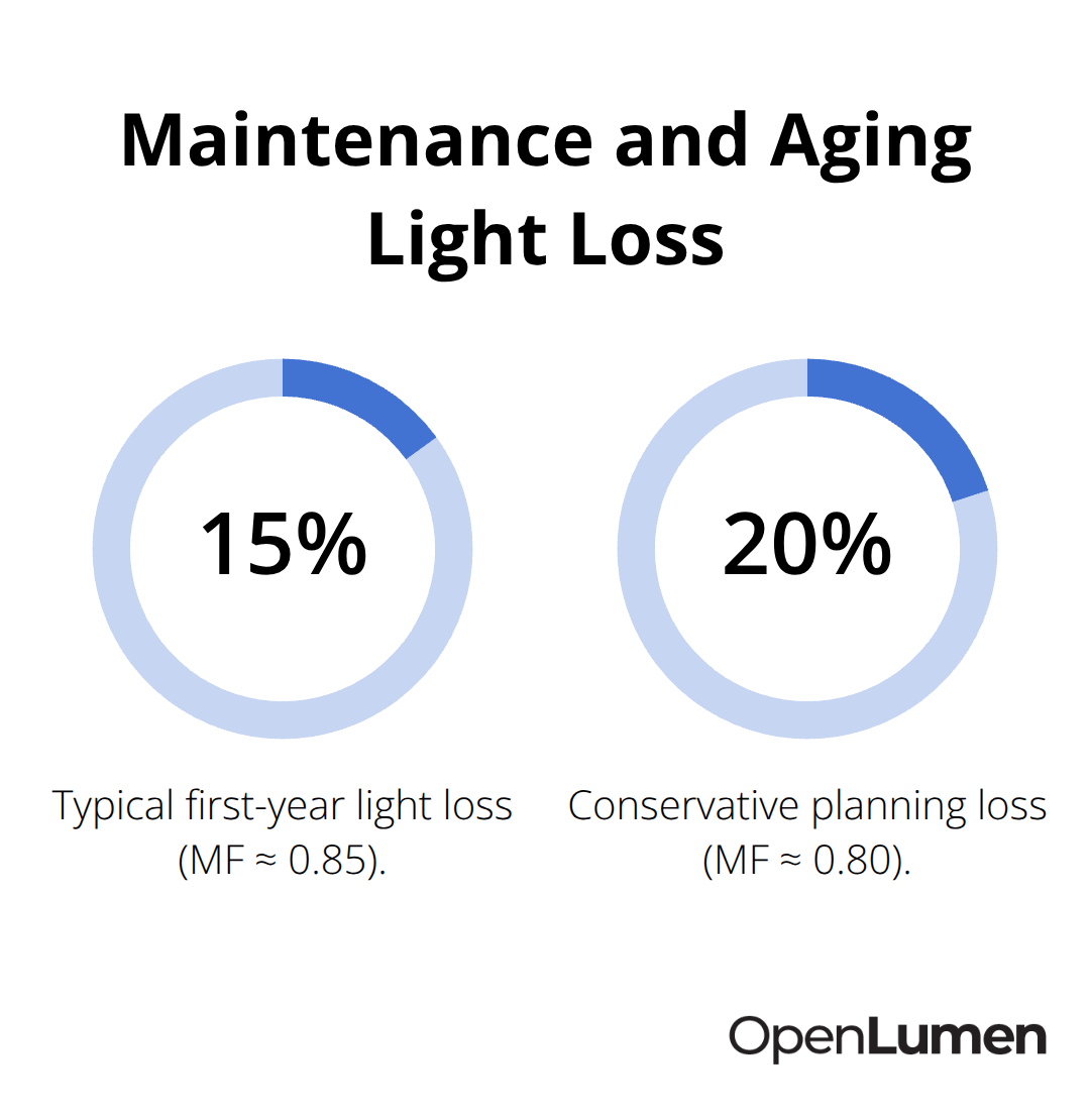
If you’re working on a renovation, measure the actual surfaces with a reflectance meter or photograph them against a known reference-guessing costs you accuracy and credibility with clients. Maintenance factor accounts for lumen depreciation and dirt buildup over time; most practitioners use 0.80 to 0.85 as a conservative estimate, meaning you should expect the system to deliver 15–20% less light after one year of operation. For outdoor installations or high-traffic areas, plan for more frequent cleaning or use the lower maintenance factor.
Extracting the Data You Actually Need
The luminaire’s IES file contains the photometric data you need, but you don’t need to memorize the curves-focus instead on extracting three critical numbers: the total lumens, the peak candela in the main beam direction, and the beam angle at 50% intensity. These three data points let you run field-ready calculations in minutes without simulation software. With real-time illuminance calculations at your fingertips, you’re ready to move into the practical calculation methods that contractors use every day on site.
How to Calculate Illuminance on Site in Minutes
The Inverse Square Law for Fast Field Estimates
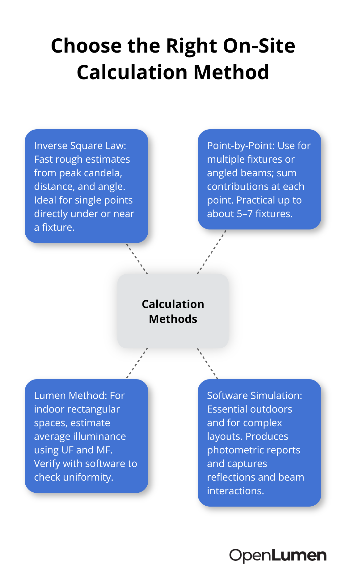
The inverse square law is your fastest tool for rough estimates, and you should memorize the formula: E = (I / d²) × cos θ. Luminous intensity I comes directly from the luminaire’s candlepower distribution curve in candela, d is the distance in meters from the fixture to your target point, and cos θ accounts for the angle between the light ray and the surface. On a horizontal surface directly below the fixture, cos θ equals 1, so the math simplifies dramatically. A practical example: if a fixture produces 2,200 candela and you measure 2.13 meters below it, the illuminance before maintenance loss is 2,200 ÷ (2.13²) = roughly 484 lux. Multiply by a light loss factor of 0.85 to account for lumen depreciation and dirt, and you get 411 lux maintained-enough for most warehouse tasks.
This method works exceptionally well on site because you extract the peak candela from the datasheet, measure or estimate the distance, and calculate in under two minutes without opening software. The speed advantage makes it invaluable when you need quick answers on the job.
Point-by-Point Calculations for Multiple Fixtures
Point-by-point calculations become necessary when fixtures mount at angles or when you need illuminance at multiple locations across a space. The same formula applies, but now you must account for the angle of incidence. If your measurement point sits off to the side, the cos θ term shrinks the result significantly; a 45-degree angle reduces illuminance to 0.707 times the vertical value. For two or more fixtures lighting the same point, use Abney’s Law and add the illuminance values together-E total = E1 + E2 + E3.
A two-fixture example from field practice shows this clearly: position one delivers 398 lux and position two delivers 291 lux, totaling 689 lux at the target point. If you work on a job site with no power or connectivity, knowing how to add illuminance contributions manually keeps you productive. The practical limit for point-by-point work is about five to seven fixtures; beyond that, simulation software becomes faster and more reliable than hand calculations.
The Lumen Method for Indoor Spaces
Software tools like Dialux, Relux, or AGI32 use ray-tracing methods to account for reflections and complex geometry that point-by-point math cannot capture. For rectangular indoor spaces under 100 meters on a side, the lumen method offers a middle ground: calculate average illuminance using E = (F × n × N × UF × MF) / A, where F is lumens per lamp, n is the number of fixtures, UF is the utilization factor from IES tables, MF is maintenance factor, and A is the floor area in square meters.
A real warehouse example shows how this works: to achieve 200 lux on a 2,500 m² floor with 19,000-lumen lamps, UF of 1.1, and MF of 0.8, you need roughly 30 fixtures. The lumen method gives you a reliable first-pass estimate in five minutes, then software verification takes another ten minutes to catch hotspots or dark corners.
Why Outdoor Calculations Demand Different Approaches
Never rely on the lumen method for outdoor applications because it ignores long-range light scatter and has no ceiling to reflect light-field results typically run 20–40% lower than the formula predicts. For outdoor parking lots or sports fields, simulation software is non-negotiable because mounting heights, pole spacing, and beam patterns interact in ways hand calculations cannot capture accurately. The complexity of outdoor geometry makes manual methods unreliable, and clients expect professional photometric reports that only software can generate.
When you move from site calculations to design verification, the tools you choose determine whether your layout meets code requirements and client expectations.
Common Mistakes in Lighting Design and How to Avoid Them
Mounting Height and Beam Angle Errors
Mounting height errors destroy more lighting designs than any other single mistake, yet most contractors estimate it rather than measure it. The inverse square law punishes careless height measurements because doubling the distance from 2 meters to 4 meters quarters your illuminance from roughly 500 lux down to 125 lux-a catastrophic drop that fails code requirements and forces expensive fixture additions mid-project. Measure mounting height to the nearest 10 centimeters on site using a laser distance meter or tape, especially on angled ceilings or sloped outdoor terrain where visual estimates fail spectacularly.
Beam angle matters equally because a fixture with a 40-degree beam angle concentrates light tightly, while a 120-degree fixture spreads the same lumens across a much wider area. Most contractors assume all high-bay fixtures spread light identically, but the luminaire’s candlepower distribution curve reveals the truth: a narrow-beam 100-watt fixture produces 2,500 candela while a wide-beam 100-watt fixture generates only 800 candela. Read the distribution curve before you calculate anything, because the peak candela value directly determines your illuminance result.
Surface Reflectance Deviations on Real Job Sites
Surface reflectance values on real job sites deviate wildly from textbook assumptions, and this deviation compounds across multiple fixtures. A warehouse ceiling that looks white in person often measures 50–60% reflectance instead of the assumed 80%, immediately reducing your average illuminance by 25–30% and forcing you to add extra fixtures after installation begins. Measure actual reflectance with a portable meter or photograph the surface against a known gray card before finalizing your design-this 15-minute investment eliminates expensive change orders.
Hotspots and Dark Zones From Multiple Sources
Multiple light sources create unpredictable hotspots and dark zones unless you calculate each fixture’s contribution separately at several points across your work plane. A common field failure occurs when contractors position three identical fixtures in a line and assume uniform coverage, only to discover that overlapping beams create a bright stripe while gaps between fixtures remain underlit. Use point-by-point calculations or simulation software to verify illuminance at minimum 5–7 measurement points across your target area, checking for uniformity ratios that typically should not exceed 3:1 (maximum illuminance divided by minimum illuminance at task level).
The EN12464-1 standard for ordinary workshop lighting specifies 300 lux with a 2:1 uniformity ratio, meaning a hotspot of 600 lux paired with a dark corner at 150 lux fails the requirement despite averaging 375 lux across the space.
Final Thoughts
Accurate site lighting calculations rest on three fundamentals: extracting the right data from luminaire specs, applying the correct formula for your situation, and verifying results against real-world conditions. The inverse square law gives you speed for rough estimates, point-by-point methods handle complex layouts, and the lumen formula bridges the gap for indoor spaces. You need all three approaches in your toolkit because job site conditions change constantly, and no single method works in isolation.
Manual calculations remain invaluable when you work on site without power or internet, when you need answers in minutes, or when you troubleshoot an existing installation. A laser distance meter, the inverse square law formula, and a basic calculator let you verify illuminance at any point without opening software. This independence builds credibility with clients and keeps projects moving when technology fails.
Digital tools become essential once your layout exceeds five to seven fixtures, when you need professional photometric reports, or when outdoor geometry demands accuracy that hand math cannot deliver. Software like Dialux or Relux captures reflections, accounts for beam interactions, and generates the visual proof that clients expect before signing off on designs. For teams managing multiple projects, OpenLumen streamlines the entire process by combining real-time illuminance analysis with a verified luminaires library, letting you design, verify, and generate reports without expensive software or steep learning curves.
The information provided is for general educational purposes only and should not be considered professional engineering or lighting design advice. Always verify project requirements, local codes, and specifications with qualified professionals before making final decisions.