Photometric layout workflows are the backbone of professional lighting design. They transform guesswork into precision, showing you exactly where light lands and how bright it gets before you install a single fixture.
At OpenLumen, we’ve seen how the right workflow cuts design time in half while eliminating costly revisions. This guide walks you through the process step by step, from setting up your space to delivering client-ready documentation.
What Photometric Layouts Actually Do
Proof of Performance Before Installation
A photometric layout proves your design works before installation happens. It shows foot-candle values at specific points across your space, uniformity ratios that reveal dark spots, and whether your design meets code requirements like IESNA standards or local energy ordinances. Without one, you gamble that your fixture selection and spacing will work-and that gamble costs money when revisions hit the job site.
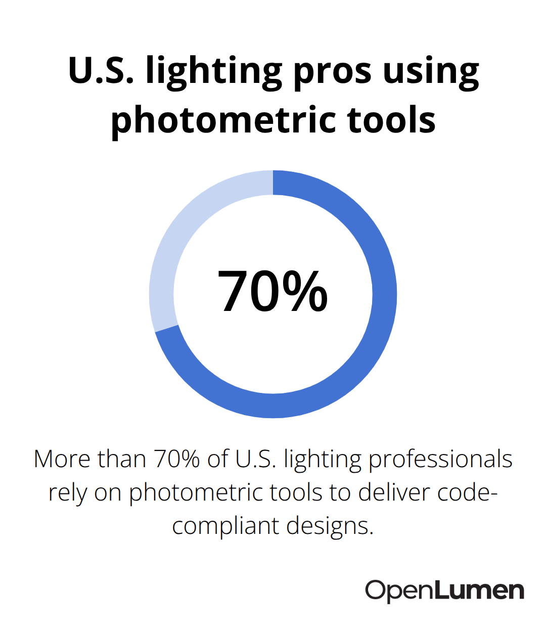
More than 70% of U.S. lighting professionals rely on photometric tools to deliver code-compliant designs, according to industry data, because the alternative is rework, delays, and unhappy clients.
The real value isn’t the pretty renderings. It’s the data that lets you swap fixtures in seconds, test different mounting heights, and validate that your layout actually solves the problem.
Why Traditional Spacing Rules Fall Short
Traditional design workflows fail because they rely on rules of thumb and spacing-to-height ratios without testing them against actual site conditions. A contractor might space wall packs 20 feet apart at 15 feet high, follow the formula, and still end up with dark corners or hot spots because they never accounted for building geometry, surface reflectivity, or obstruction from trees.
Modern photometric tools eliminate this guesswork. You input real site data-exact dimensions, wall materials, mounting positions, and target illuminance levels-then instantly see where light actually lands. When you place a luminaire, the foot-candle map updates immediately, the fixture count refreshes, and you catch problems before the design leaves your desk.
Real-Time Calculation Cuts Design Cycles
Tools built directly into CAD environments (like DM Photometrics in AutoCAD) let you place a fixture, run calculations, and update your schedule in real time without jumping between applications. You no longer wait for external software to process your changes. Instead, you work inside the environment your team already uses, which means faster iteration and fewer file-handling headaches across electrical, site, and architectural disciplines.
This speed matters. When you test three different fixture layouts in the time it used to take to test one, you find better solutions and catch code violations early. The result: designs that work the first time and clients who see faster approvals.
Moving Forward With Confidence
Once you understand what photometric layouts reveal about your design, the next step is setting up your project correctly so those calculations reflect real-world conditions.
Building Your Project Foundation
Measure Your Space and Set Reflectance Values
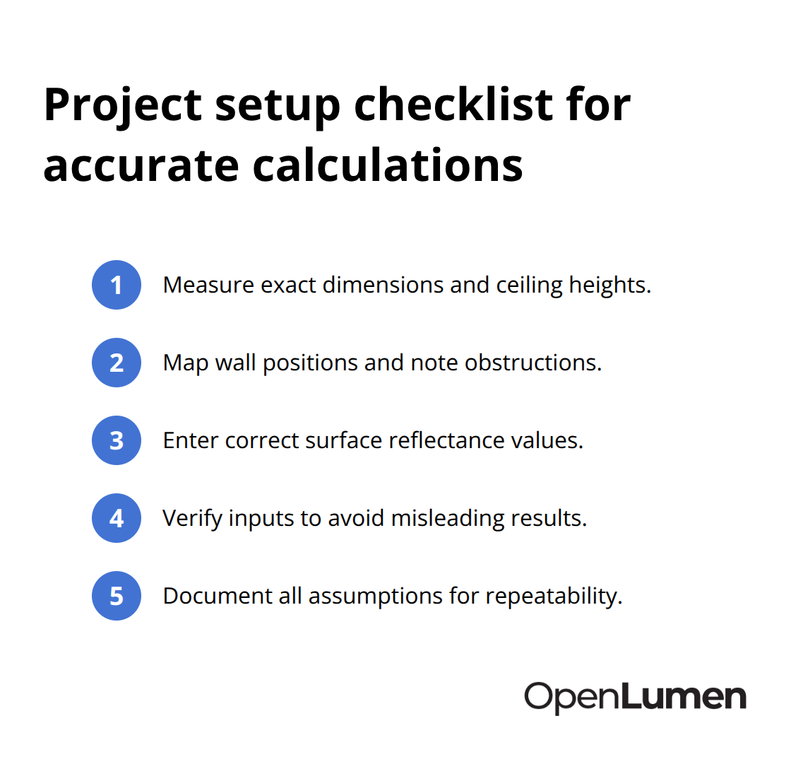
Accurate project setup determines whether your photometric calculations match real conditions or produce misleading results. Measure your space precisely-exact dimensions, ceiling heights, wall positions, and any obstructions all affect the outcome. Input your surface reflectance values correctly: most drywall runs 50–70% reflectance, concrete 20–40%, and asphalt 5–15%. Wrong reflectance kills accuracy and forces you to recalculate everything later.
Define Target Illuminance From Code Requirements
Define your target illuminance based on the actual task, not guesswork. A fueling area needs 20–30 foot-candles, a parking lot perimeter might require only 0.5 foot-candles, and a loading dock typically demands 30–50 foot-candles. These values come from IESNA standards and local energy codes, so verify your jurisdiction’s requirements before you calculate. Skipping this step means your design fails inspection or wastes energy on over-lit spaces.
Select Mounting Height and Test Spacing
Mount heights matter for fixture selection and spacing. Most parking lots work best at 15–20 feet; lower heights (10–12 feet) suit walkways and building facades. Once you set height, your spacing-to-height ratio (SHR) becomes your guide-an SHR of 1.3 at 15 feet means roughly 20 feet center-to-center spacing, but only as a starting point, not a final answer. Real-time tools let you test this immediately. Place your first fixture, run calculations, and check uniformity ratios. You want minimum-to-average ratios above 0.4 for most exterior spaces to avoid dark pockets.
Iterate Fixture Placement and Distribution Type
If you see dark corners, adjust mounting height or add fixtures rather than guessing. Test different fixture distributions: Type II works for narrow facades, Type III for broader coverage, and Type IV for deep yard-side throw. Swap fixtures in seconds using your tool’s library-most platforms include thousands of manufacturer files so you compare performance without re-entering data. Check property-line performance immediately; dark-sky compliance requires 0 foot-candles at the boundary in many jurisdictions, so your layout must prove it meets this before the client approves.
Run Dense Calculations and Validate Results
Run your calculations at 10–20 foot intervals across the space, not just at a few sample points, to catch uniformity problems early. When you spot a hot spot or dark zone, move a fixture slightly, re-run calculations, and verify the fix works-this iterative process takes minutes with modern tools, not hours with manual worksheets. Once your layout passes uniformity checks and meets code requirements at the property line, you move to the next critical phase: extracting the metrics that prove your design works and preparing the documentation your client needs to approve and install it.
Extracting and Presenting Your Photometric Data
Your calculations are complete, but raw numbers mean nothing to clients or inspectors. You need to translate foot-candle maps, uniformity ratios, and compliance checks into clear documentation that justifies your design and speeds approvals.
Identify the Metrics That Matter for Your Project
Start with the specific metrics your project demands. For a parking lot, you need average illuminance, minimum-to-average uniformity ratio, maximum-to-minimum ratio, and BUG ratings to prove dark-sky compliance. For a loading dock, focus on average foot-candles across the work surface, hot-spot verification (maximum values), and whether shadows from obstructions create unsafe zones. IESNA standards define these requirements, but many jurisdictions add their own rules, so verify what your local code actually demands before you generate reports.
Create Visual Documentation That Clients Understand
Extract isoline contour drawings directly from your photometric tool-these show constant foot-candle levels and instantly reveal coverage gaps or over-lit zones that numbers alone would hide. Include a false-color rendering alongside the contours; clients understand visual output faster than spreadsheets, and it builds confidence that your design solves their problem. Add a fixture schedule showing every luminaire’s location, type, mounting height, wattage, and color temperature. This schedule becomes your installation guide and proves you haven’t over-specified or under-lit the space. Most tools auto-generate this from your layout, so there’s no manual counting.
Build Documentation That Wins Approvals
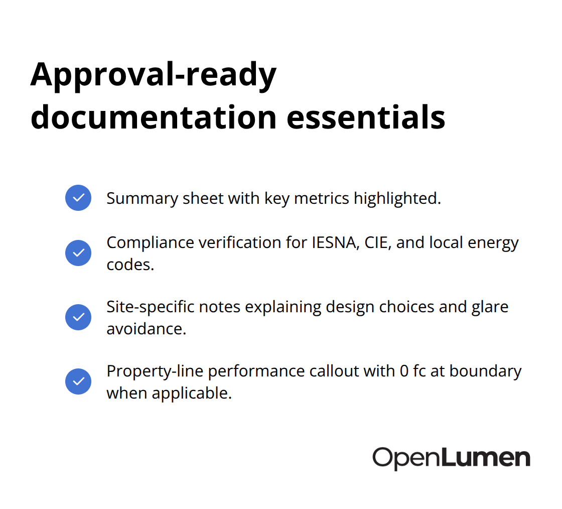
Documentation that wins approvals includes three specific components: a summary sheet with key metrics highlighted (average foot-candles, uniformity ratios, total fixture count, estimated energy consumption), compliance verification showing how your design meets IESNA, CIE, and local energy codes, and site-specific notes explaining design choices like why you selected Type III distribution or why you positioned fixtures to avoid glare at occupied windows. Property-line performance deserves its own callout-show that your design achieves 0 foot-candles at the boundary if dark-sky rules apply, or document the actual spillage if local code permits it.
Test Alternatives and Show Your Work
When you swap fixtures to optimize cost or performance, regenerate your reports immediately and show the client before-and-after comparisons; this demonstrates that you tested alternatives and picked the best solution, not the first one. Include a night-verification checklist in your documentation that outlines what the installation crew should check on-site-dark pockets to watch for, camera blind spots to confirm, and aiming tolerances that matter. This transforms your report from a static approval document into an installation guide that prevents field mistakes.
Document Everything for Future Reference
Save all layouts, IES file references, and control settings in a maintenance log attached to the documentation; future service calls or modifications become faster because the next technician knows exactly what fixtures you specified and why. This record also protects you if questions arise about design decisions months or years after installation.
Final Thoughts
Photometric layout workflows transform how you approach lighting design. You now understand how to set up projects with accurate dimensions and reflectance values, test fixture placement in real time, and extract the metrics that prove your design meets code before installation begins. This systematic approach eliminates costly field revisions and accelerates client approvals across every project type.
The speed advantage compounds when you work with tools that update calculations instantly inside your existing CAD environment. You test three fixture layouts in the time traditional methods required for one, catch dark spots and hot spots before they become expensive problems, and generate client-ready documentation automatically. This efficiency transforms photometric design from a compliance burden into a competitive edge that sets your work apart.
Starting your photometric layout workflow requires only accurate project setup and a platform that delivers real-time analysis. OpenLumen lets you create layouts, run calculations, and generate professional reports in a browser without steep learning curves or licensing barriers. Pick a project, set up your space accurately, and test your first layout to experience how much faster and more reliable this approach is compared to traditional methods.
The information provided is for general educational purposes only and should not be considered professional engineering or lighting design advice. Always verify project requirements, local codes, and specifications with qualified professionals before making final decisions.